Tranz4mr’s-AF 30B Page


Tranz4mr’s-AF 30B Page


American Flyer 30B Checkout & Repair (300 Watt Output)
1. UNPLUG THE POWER CORD FROM THE WALL OUTLET
2. Check the bakelite case for cracks.
3. Turn each of the 6 terminal lugs until they are tight. If a terminal turns past tight then the terminal stud needs to be tightened later once the cover is removed.
1. Carefully check the power cord for cracks and or missing bits of Insulation.
2. If the cord is good set the 2 handles to the zero position and the center on/off switch to off.
3. Plug the power cord into a wall outlet.
4. Turn the center on/off switch to on. The center green light should be lit. If not replace the bulb with a #1445 bulb.
Left & Right Throttle Circuit Tests
5. Connect an AC voltmeter to the base terminal and to the left
5-18 V terminal.
6. Slowly bring up the left throttle while watching the AC voltmeter. The voltage should start at 4 to 6 volts and rise slowly and steadily up to between 16.5 and 18 volts. The dial on the voltmeter on the face of the 30B should also rise with the rotation of the throttle. The starting and final voltage depends on your home power voltage. If the voltage is not steady or is out of range you might have a problem. If the built in voltmeter on the face of the transformer doesn’t function make a note of it so that it can be fixed or replaced later.
7. Turn the left throttle back to the zero position.
8. Lift the throttle handle arm up to the dead man off position. Slowly rotate the throttle to full while watching that the voltmeter reads zero volts through the full rotation. If the voltage jumps up any where in the throttle rotation the roller arms will need to be adjusted latter up from the transformer core.
9. Disconnect the AC voltmeter from the base and 5-18 V terminals.
10. Short across the left base and left 5-18V terminals with a metal screwdriver shaft.
11. Slowly bring up the left handle while watching the left red Light and listening to the transformer. The circuit breaker should trip making a noise and the left red light should be lit. If the breaker doesn't trip it needs to be checked and possibly replaced later. If the red light isn’t lit replace the bulb with a #1445 bulb and repeat steps 10-13.
12. Quickly remove the screwdriver shaft and turn the left throttle back to the 0 position. The left red Light should turn off.
13. Repeat steps 8 and 15 with the right throttle.
18Volt Fixed Circuit Tests
14.Turn the center on/off switch to off.
15. Connect the AC voltmeter to a base and a 18 V terminal.
16.Turn the center on/off switch to on. The AC voltmeter should read a steady 15-18 volts.
17.Turn the center on/off switch to off.
18. Using a heavy gauge wire short from one of the base terminals to one of the 18 V terminals.
19. Turn the center on/off switch to on. The circuit breaker should trip immediately.
20. Quickly turn the center on/off switch to off and remove the heavy gauge shorting wire.
21. UNPLUG THE POWER CORD FROM THE WALL OUTLET
External Inspection
This is for the newest version with the rollers attached to the handles (photo #6) as opposed to the older 2 piece roller arm where the roller is attached to the core. The American Flyer 30B transformer has 2 separate variable voltage circuits and breakers for the left and right throttles. There is a 3rd circuit and breaker for the two 18 volt fixed terminals. Test the 3 separate circuits and breakers using the following steps.
1. UNPLUG THE POWER CORD FROM THE WALL OUTLET
2. Remove the 3 lens covers from the top cover.
3. Remove the 3 light bulbs.
4. Turn the transformer on its side and remove the 4 slot head screws that hold the top cover on. Photo #3.
5. Turn the transformer face up and slowly lift up the top cover. You can’t remove the cover until you remove the nut from the center power switch
6. Slide your hand inside and hold the back of the power switch.
7. Using a 9/16” wrench remove the On/Off switch nut. Photo #4.
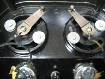
8. Lift the cover up higher to expose the back of the volt meters.
9. Remove the nuts holding the wires to the back of the voltmeters. Photo #5.
10. Remove the wires from the back of the two throttle handles.
11. You should be able to remove the cover now.
1. Check that the 2 carbon rollers are in good shape and roll easily. No flat spots or chips! If any are bad or worn out replace them.
See Photo #9
2. Check for loose solder joints especially on the larger wires. If they are loose re-solder them.
3. Check for broken wires. Especially the 2 that were attached to the back of the throttle handles. These have a tendency to break. This is the most common failure! Photo #7
4. Check for wires that are burned or where insulation is falling off. Replace the insulation with shrink tube or replace the wire.
5. Replace the power cord if it has cracks or missing insulation.
6. If the throttles don’t turn smoothly remove the 2 slotted screws washers and spring washers in the back of each throttle. Photo #8
7. The throttle handles will now pull off for cleaning.
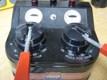
Photo #1 - American Flyer 30B
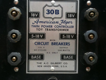
Photo #2 - Terminals
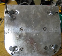
Photo #3 - Remove 4 slot head screws
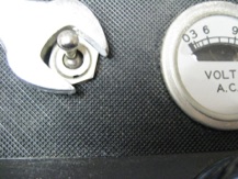
Photo #4 - On/Off Switch Nut
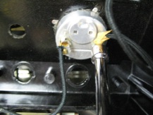
Photo #5 - Remove the (4) nuts from Power Meters.
1. If the carbon rollers are worn out remove them by crushing them with a pair of needle nose pliers.
2. Remove the roller pins by cutting them with a pair of wire cutters. Photo #10
NOTE!
Original American Flyer pins and rollers, as well as the tool to crimp the pin, are hard to find. They can be found but I still haven’t found a good tool to crimp them.
See the original AF carbon roller and pin in Photo #9.
The easiest way to replace the carbon rollers is to order Lionel postwar ZW rollers, part number V-45. For the pins use 1/16” diameter x 3/4” long cotter pins. ZW rollers are larger and should last longer plus they cost about 50 cents.
3. Insert the 1/16” diameter (.060”) cotter pin through the arm and carbon roller from the throttle center out. See Photo #11.
4. Bend the two legs of the cotter pin and trim off some of the excess. See Photo #11.
5. Make sure that the two Roller Arms clear each other when rotated. See Photo #12.
6. If the rollers contacted the core when the dead man throttle arm was rotated now is a good time to bend the roller arms up toward the cover slightly. Using a pair of needle nose pliers grap the arm near the bend near the center and bend slightly up towards the cover. Be sure to repeat the checkout when everything is reassembled. More adjustment might be needed.
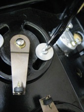
Photo #8 - Remove Throttle Handles.
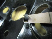
Photo #9 - Original AF Carbon Roller and Crimped Pin.
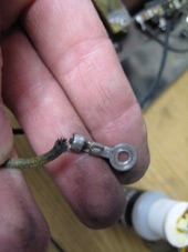
Photo #7 - Broken Throttle Wire.
1. Remove the meter by bending the 4 tabs back up against the side of the meter and pushing out from the back.
2. Set the meter face down and rotate the back cover Counter Clockwise on the face frame until the small tabs align with the slots next to the big tabs. See Photo #13 & 14.
3. Remove the Face frame, Glass, Silver Paper Scale and Inner Frame. See Photo #15.
CAUTION!
The Pointer is extremely delicate and is easily bent.
Don’t touch it!
4. Using an Ohmmeter measure the resistance across the the resistor. It should measure 69 ohms. The resistor is usually what fails .
5. To replace the resistor snip the tiny wire soldered to one end.
See Photo #16.
6. Remove the screw that the resistor is attached to by removing the nut on the back. See Photo # 17.
7. Solder a new 69 ohm resistor to the head of the screw and reinstall in the meter housing. See Photo #18 and #19.
8. Wrap the tiny wire around the free end of the resistor and solder using a heat sink to protect the resistor. See Photos #19 - #21.
9. Replace the Inner Frame, Silver Paper Scale and glass on the meter housing. Apply about 10 volts AC and make sure the pointer moves smoothly and doesn’t hit anything. Adjust the pointer gently if needed.
10. Reassemble and reinstall the meter.
11. Sometimes the pointer contact bearing points on the frame are too tight and the pointer wont rotate on its axis. The fix for this is to remove the other nut on the back and very carefully remove the whole mechanism.
12. very gently bend the frame opening loosening up the pressure on the 2 contact bearing points. Usually the pointer mechanism will come loose and you will have a fun time getting it back together. When you are done the pinter should rotate freely.
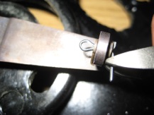
Photo #11 - Install ZW Roller and Cotter Pin.
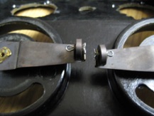
Photo #12 - Roller Arm Clearance.
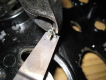
Photo #10 - Cut the pin with a pair of Wire Cutters.
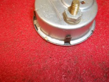
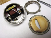
Photo #15 - Remove Face Frame, Paper Scale, Glass and Inner Frame
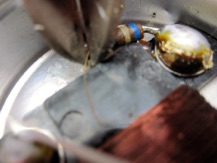
Photo #16- Snip the tiny wire soldered to the resistor
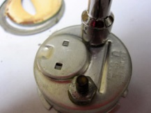
Photo #17- Remove the nut holding the screw and resistor.
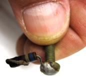
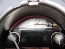
Photo #19- Remove the nut holding the screw and resistor.
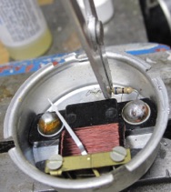
Photo #20- Solder using a heat sink.
Photo #21- Tiny wire soldered to the free end of the resistor.
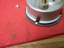
Photo #14 - Small tabs and big tabs lined up.
1. A slight 60 Hz buzzing is normal with 30b transformers. If the noise is excessive there are a couple ways to reduce the noise.
2. Remove the top cover and back cover.
3. Tighten the four 3/8” nuts between the core and the bottom plate using a screwdriver on top and a thin 3/8” ignition wrench on the nut. See photo #22
4. Turn the transformer over and using a 3/8” socket tighten the four nuts that hold the core to the base. See Photo #23
5. If you still have too much noise unplug the transformer.
6. Using a hammer and a piece of hardwood drive the existing wooden wedge between the core and the coil in a little bit. There is one wedge in the front of the core and one wedge in the back.
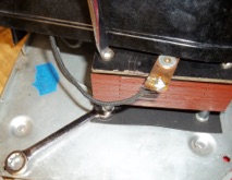
Photo #22- Tiny wire soldered to the free end of the resistor.
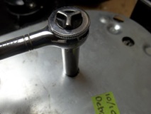
Photo #23- Tighten the 4 nuts on the bottom.
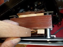
Photo #25- Drive the wooden wedges in. Front wedge.
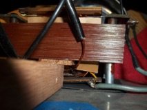
Photo #24- Drive the wooden wedges in. Back wedge.


Remove the Cover
Internal Inspection
Replace the Rollers
Repair Broken Meters
Quieting Buzzing Transformers