Tranz4mr’s ZW Page


Tranz4mr’s ZW Page


Replacing ZW Whistle Rectifier Discs with Diodes
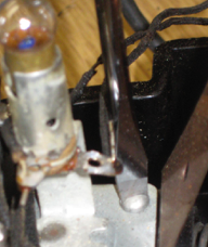
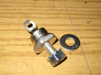
All Postwar ZW’s use inexpensive rectifier discs to create the DC that trips the whistle solenoid in pre and postwar trains. In modern trains it activates the electronic whistle. Eventually these discs fail and must be replaced. The best replacement is a stud mounted, anode to case rectifier diode. Model 1N1190AR, or 1N1186AR available online. The 1N1190AR is a 600V 40 Amp diode with a threaded 1/4”-28 stud mount. Use the steps that follow to replace the original rectifier disks. See Photo 1. NOTE: I have switched suppliers to sources on Ebay as supplies on Anode to Case Diodes have tightened up.
Diode Installation
•Remove the Red and Green lens covers from the ZW.
•Remove the 2 light bulbs.
•Remove the 4 bolts that hold the ZW top cover on.
•Remove the ZW top cover.
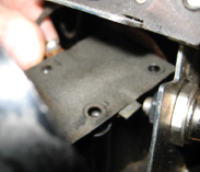
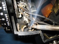
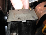
•Remove the 2 screws holding down the Whistle Switch Assembly.
Photo 2.
Photo #2 - Remove the 2 screws
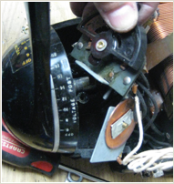
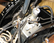
•Carefully lift up the Whistle Switch
Assembly. Photo 3.
•Watch out for the flat piece of
insulation under it and the insulation
under that with the 4 fingers.
Photos 4 & 5
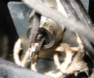
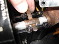
•Use a small flat bladed screwdriver to pry off the Speed Nut with the black wire that is holding the old Rectifier Disc in place. Photo 6.
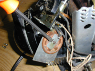
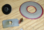
•Remove the old Rectifier Disc , Stud and Fiber Washers. Photo 7.
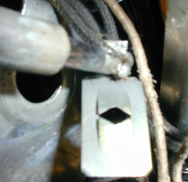
Photo #8 - Remove the Black Wire from the Speed Nut.
•Use a soldering iron to remove the Black Wire from the Speed Nut. Photos 7 & 8.
DO NOT REMOVE THE WHITE WIRE shown in Photo 9 & 10.
Diode Installation
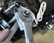
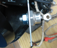
•Install the new Diode to the Whistle Switch Assembly Bracket in the same hole that the Rectifier Disc was in. Use 11/16” and a 7/16” wrenches to tighten the Diode securely.
Photos 9 & 10.
•Insert the Black Wire through the hole in the end of the Diode.
Photo 11.
•Solder the Black Wire to the end of the Diode. Photo 12
Reassembly
•Clean the brass Spring Contact and the Shaft with a Dremel wire wheel. Photo 13.
•Apply a light coat of clear teflon grease under the spring contact and on the shaft where it contacts the case. Photo 13.
• Hold the Spring Contact in place for reassembly. Photo 13.

•Install the Spring Contact Insulation with the 4 fingers over the Shaft & Spring Contact. Make sure that the 4 vertical fingers are bent down and go in alongside the shaft. Photo 14.
•Install the Flat Insulation over the Spring Contact Insulation.
Photo 15.
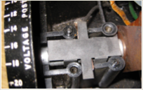
•Reinstall the Whistle Switch Assembly . Install and tighten the
2 round head screws. Photo 16.
•Reinstall the ZW top cover.
•Reinstall the 4 screws that hold the ZW top cover on.
•Reinstall the 2 light bulbs.
•Reinstall the Red and Green lens covers from the ZW.
•Repeat everything above for the Diode on the other side of the transformer.